Last day I was surfing hackaday and read this nice post on laser cut and printable casing.
I really liked Riley Porter laser cut frame.
Here is a exmample of his work.

After seen the hackaday post I realise that I also use the laser cutter for the casing of my school project I did last semester with my team. Mine is different so I decided to write this post to share my ideas.
This page will talk about my school project and will go in details about specific parts of it:
- How to assemble surface mount component with solderpaste and oven.
- Mistake we made during the project and how we will correct them next semester.
- The schematic and PCB explanation.
- How to make a laser engrave case for you project.
Last semester, we learn about embedded system (my favorite topic), we learn Microchip PIC, Texas Instrument DSP, digital filters, all the basic I2C, SPI, serial, ADC, etc. The project we had to build had to have a DSP that communicated with a PIC. The remote (PIC) had to be battery powered and had to have a LCD. The PIC was programmed in assembly and the DSP in C. Our team decided to build a sport accelerometer. That idea came from one of the University coach that teach pole vaulting. He told us, that he needs a device to tell him and the athlete there mistake when they run.
You see, when the athlete runs and gets ready to set the pole in the notch in the floor, they slow down when they approach the hole. Technically, you never slow down, you need to calculate every single step and be dead on when you insert the pole in the notch. Beginner will tend to slow down there pace, by making smaller steps towards the end to be synchronise when the pole reach the hole. That is big NO NO.
So the coach wanted a device to log all those info on the computer and also indicate with a buzzing sound when the athlete made a mistake. (the buzzer was really optionnal)


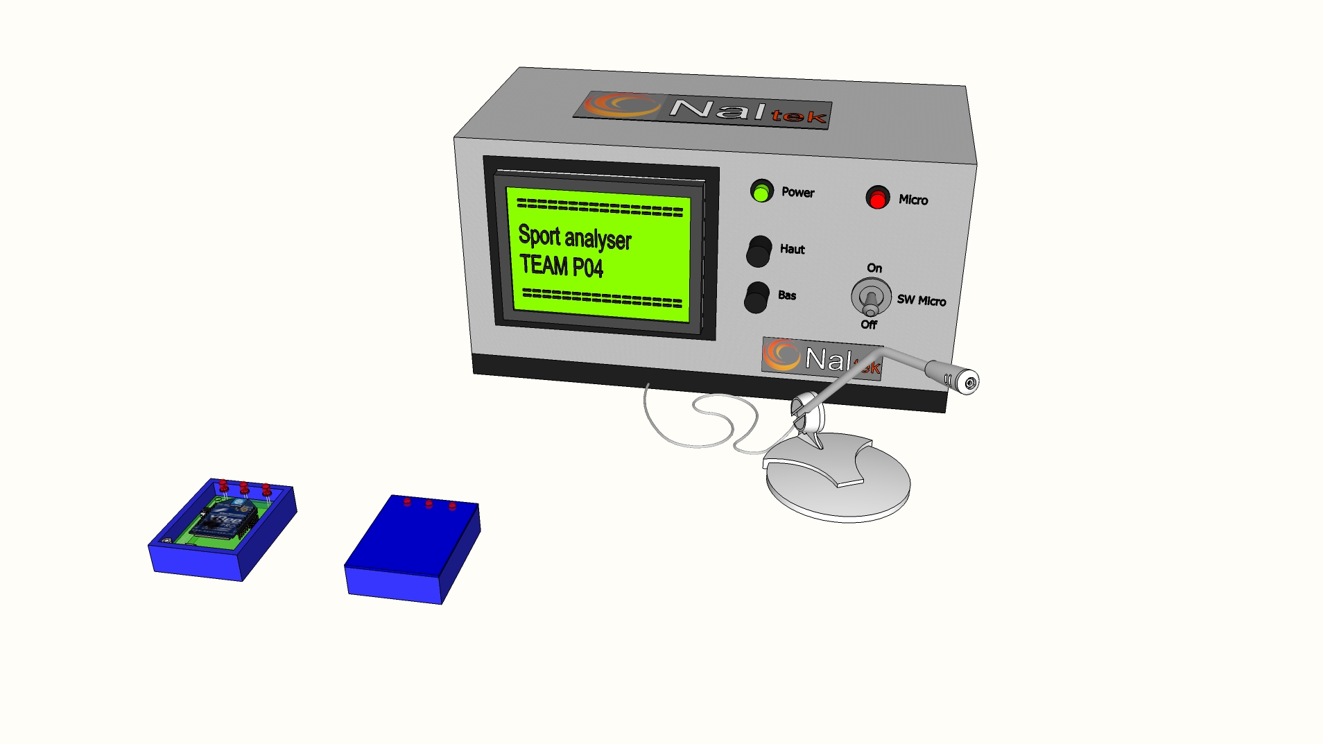
So here is the final prototype that we presented for our class.

In this particular picture, we have added all the holes for the development of the device, there is the programming header call ICD ( In circuit Debugger, which let us program the microcontroller inside), just above the power label that is the serial lines and above the ON/OFF switch that is the external power. All those added header where there has backup is something when wrong. If we lost wireless connection, we could plug wire directly in the header or bring power if we got low battery.


This is the top cover without the debugging marking. Those cover where laser cut/engrave from my sponsor Solarbotics. I will tell more on how I made it at the end of this article.
Let see the inside!

Those are the two printed cricuit board (PCB) we got made at school with our PCB engraver, the via are also plated!


Here is the PCB that was done in eagle.

The complete schematic. On the top right of the schematic we have a LDO (Low Drop Out voltage regulator) from Microchip, the part number in the schematic is wrong, I took a random part that had the right PCB part. ( that was a mistake, I end up with problems, I talk about that mistake in the PCB assembly section) The bottom left is the lithium battery charger. On the middle right part we have the Xbee and on middle left part we have the accelerometer. It is pretty straight forward.
We also had a Texas Instrument DSP ( Digital Signal Processing) and we had to do sound recognition of a guitare note. The guitare note was mandatory for all the teams. We also had to implement a other sound detection. We use a whistle to start the data logging.

The block diagram you see there was the first idea and we wanted to add a GLCD touch screen (Graphic LCD) on there and ehternet.

This is the block diagram of the remote alone. We also had to use a specific PIC since the assemble structure is different from a 16F or 18F and I did not want to mess with my team mate who never did PIC assembly before.
It was not a big deal since we got a 28 pin 18F PIC.
PCB ASSEMBLY_________
Here are some pictures of me assembling the PCB.

This above picture resume everything about PCB assembly. Can you see that foot pedal? That is connected to the machine that is behind the magnifing glass/lamp. I use my feet to activate the syringe you see below. That seringue hold solder paste, which is ultra tiny spheres of solder in form of a paste. When that paste is heated, all those marble melt to solder the part it is touching.
Solder paste consist of a mixture of tiny spherical solder particles and flux.
Solder particles
- Source of solder required to form the sodler joint
Flux
- Carries the solder particles
- Provides tackiness to hold components prior to soldering
- Cleans the surface of the pads and leads
- Protects pads and leads from further oxidation during soldering

Digikey part number KE1507-ND

Here is the machine, you can adjust the pressure you put in the syringe and other stuff. I did not touch or adjust anything there, It was ready to use. I guest, by the look of the top portion of the machine, that you can connect a manual pick & place machine.


If you are a fan of Sparkfun you will notice some parts that comes from Sparkfun. USB connector, piezo, 3,7V lithium battery, lithium battery connector, the lithium battery charger, etc. We also got the Xbee female header (not in picture). Since we had a little budget and our University orders from Sparkfun all the time, we thought that is was a good move to use all there parts. I decided to use eagle for my schematic and PCB editor for one simple reason: Sparkfun give there parts library! I simply had to draw the schematic and then design the PCB without the need to make footprint. Time saver! (Thanks Sparkfun)
Remember don’t trust other people footprint, I had not problem with sparkfun library, but is always a very good pratice to print the PCB layout on a sheet of paper with a 1:1 ratio to check if all parts fit on it.
I admit that I did a mistake and got the wrong pinout of the voltage regulator. I did not find the part, so I took a normal regulator and added the right package put wrong footprint.
When you have finish up putting all the parts together, it is time for the oven! It took 35min to pre heat that monster. It is a conveyor type oven.


You simply drop the PCB at the front end

Take picture of it before it enters 🙂

It is in there! It took about 2-3 minutes to go throught that oven. In that picures, it shows the temperature curve that you need to reach before fully soldering the board.

It is now getting out of the oven.

You need to let the PCB cold down. You can clearlly see the distoration of the heat affecting the PCB.
I don’t know why I did not get the PIC on that board. I hand soldered the PIC later on, because I think I was waiting for samples. 😛

Here is the final board. You can see the mistake I made. First, the top two red wire are the mistake of the wrong foot print of that regulator. The white wire over the PIC is new mistake that I will rememeber for a very long time. We use a PIC18LF2550, that specific PIC has USB. Here is the pin out.

I hook my piezo buzzer on RC4 and it did not work. Simply because on the PIC, the D- and D+ are input only! It turns out that I was not the only one in my class who did the same mistake!
MECHANICAL_________
We wanted our final design to look professional so we made this nice little casing. I have a milling machine in my basement so I made it (a machine tool used to machine solid materials). I had a lot of fun making this.

Pretty dead simple, hold down you piece and start digging into it. I use Sparkfun 3.7V lithium battery under the PCB, so that is why you can see this two layer lip. The PCB will rest on there.

Those LED where just temporally soldered there to test the board.

Before cutting the LED, I wanted to be sure of the depth of the PCB into the casing.


Like you seen at the beginning, we had two PCB, so we built two of those moodules. The second one is not in a casing, we made this very elegant case/structure.


I remove the metal spacer to get the wire of the battery connector. Without removing the spacer, the wire could not fit properly. It is also a flaw in the design… I don’t want to admit it 😛 lol
It was intentionally design to fit in the machined housing so that is why the connector is sideway and not facing outward.

I am very proud of that little idea, I think is turn out very nice


The 4/40 screws where longer and I added washer. Then, I took some groomet that are normally use to protect electric wire that goes throught metal casing. They slip in perfectly on those 4/40 screws. That also is pretty darn nice!


Wolverine!!

This is how we charge the device.
CASING_(HOW-TO)_______
This is how we designed the laser cut acrylic casing.

When you PCB is done, you simply export into a image. That will create a image with a ratio of 1:1. Then I open corelDRAW to make the casing outline.

When the image is imported, I made sure that the ratio was correct, and measure it using a line and checked the dimension.
 In the above picture, I highlighted the circle in yellow. I made those really big so you can see. When corelDRAW is use with a laser, all the lines in the software need to be “hairline” (line thickness) and all other line bigger will not be laser cut. In the picture above, there are big thick yellow lines so you can see them clearly. I made circle that fit over the LED, connectors holes and also the mounting pads. On the image, you can some big white text, it is white so you can see it, that is the text that will be engraved on the acrylic, see below:
 So it looks like this, don’t forget to add WOLVERINE! The black text will be engraved (Raster) on the acrylic and the blue will be laser cut.
You simply print the file and select the laser has the printer and that is it!
The laser is my favorite toys at Solarbotics… 2 weeks after I left my boss Dave did something wrong with the laser and look how happen!!!!!

You can see more here (beware these pictures can be troubling to some geeks)

Like you can see, I really loved that laser! That picture was taken 3 week before the fatal destruction. R.I.P. super epilog laser!

Vincent Boiselle Joël P. Desroches Michaël Vachon
Jérôme Demers Alexandre Ramsay Jérôme Vallée
Steven Jolley Patrice Robichaud
Here is the dream team!

 This is the flyer we made for our project. 🙂 It is pretty slick!
CONCLUSION_________
If we redo this circuit, I would simply a lot of things, it is big and we don’t really need Xbee, bluetooth module are very small but expensive. I could use the same principal of Alexander Weber Remote Accelerometer:
http://tinkerlog.com/2010/02/07/remote-accelerometer/

He made something really small that is exactly what I build. He used a simple 868 MHz radio transceiver.
We also learn to get the breaboard/PCB prototype ready to be test really soon so we can make it work faster and find bugs. Also the SMT accelerometer was big problem since we had problem with one channel not working, and the others had not the proper output values. I then soldered a new chip and we where able to get 2 working channel. Then we realise that we should added a gyro to help and get proper data for data plotting.
We should of bought this from sparkfun. When we made a part list from Sparkfun, It was a debate if we had to spend 25$ on that module or not.

This would of save us time and frustration.
Also, out project was really simple compared to other teams, that is a very good point since we where able to finish it and have a very good grade. I think we got A or A+. One team had this very interesting project but too complex and got B. Remember this -> KISS: Keep It Simple Stupid!
Here are some tips:
- Get a working prototype fast
- Order extra part just in case
- Do not operate LASER unattended, got it DAVE?
- Test you serial communication with a wire before testing the wireless. Also test with the lowest BAUD rate before getting faster.
- Wolverine is always there to protect your project against Murphy law! (Well… That might not be true. Maybe we should try someone else… Chuck Norris!)
Here is one last funny incident that happen. The day before the final presentation we had our entire project hook up on a power supply. The knobs of the power supply was set to 5V. The layout of that specific lab lets you go behind the workbench where you find the back of the power supply and all the other instruments. Our team mate Patrice was behind the bench with is arm over the power supply and all the other instrument talking to the guys testing the circuit. We where all around that desk. Then we was completely daydreaming and started to play with random knobs of the multimeter, scope ,signal generator and… you guest it, the one and only knobs that was set to 5V of our entire circuit. We heard the power supply protection activated going “CLICK A CLICK A CLICK!” and the amperage LED repeatedly going On/Off! He got it got up to 18V, turning silicone to smoke! That was really funny!
We just started our new semester project and it will be simple! We are making a smart grid, we will have total control of your electronic in your house…